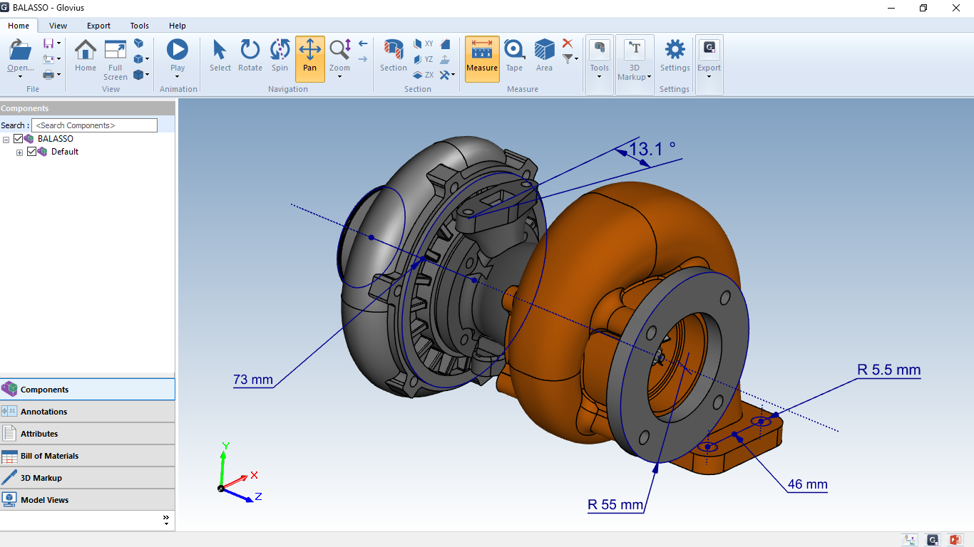

The original object is replaced with a new array object with a new default name.Once you finalize the attributes of your new array, click the OK button of the Array Dialog to create the array object.A dialog pops up on the lower right corner of the screen where you can change the number of elements and the element spacing along the three principal axes.By default, the ghost of a 2×2 array of the selected object appears in the project workspace.Measuring the angle between two object edges.įUNCTION: Replicates an object and forms an array of its clones based on a specified linear, rectangular or cubic grid A dialog pops up at the lower right corner of the screen showing the angle between the two legs in degrees as well as the X, Y, Z components of the unit vectors along the two selected edges.

Click on the second edge of the same object or another object to establish the second leg.Click on the first edge to establish the first leg.Note that while alignment of box or rectangle strip objects is intuitive, alignment of other objects is based on the faces of their bounding boxes and may not be as intuitive.įUNCTION: Measures the angle between any two edges belonging to the same object or to different objects in degrees If three principal directions are checked for alignment, the object(s) are effectively aligned by a vertex or node. SPECIAL CASES OR EXCEPTIONS: If two principal directions are checked for alignment, the object(s) are effectively aligned by an edge. For each of the selected alignment directions, enter a value for the coordinate plane where you want to move the specified faces of the selected objects.For each of the selected alignment directions, select the positive or negative face.Check all the direction boxes for the alignment. FUNCTION: Aligns one or more objects by the specified face(s) of their bounding box along the specified coordinate plane(s).


 0 kommentar(er)
